from: http://blog.163.com/pz124578@126/blog/static/235226942012359378933/
For the latest version of the code, which may contain the latest enhancements and corrections, please download the latest version of the Accord.NET Framework.
Contents

Introduction
The Accord.NET Framework is a relatively new extension framework for AForge.NET, a popular framework for computer vision and artificial intelligence. Accord.NET implements tools and features that are still not available in AForge.NET, such as Kernel Support Vector Machines, Discriminative and Projective Analysis, Hidden Markov Models, new Neural networks learning algorithms, new imaging filters, and other useful methods and tools. Accord.NET allows, among other things, to develop programs for automatic image stitching and possibly for automatic panorama creation.
A panorama is a picture that is made by combining a series of photos into one large picture. By combining a series of photos, it is possible to provide a complete view of an area or location that cannot fit in a single shot.
In the example below, we will demonstrate how to use features already available in Accord.NET to stitch two images together and create a simple and small panorama. In the last section, we will discuss ways to generalize the method for multiple pairs of images, creating full blown image mosaics.

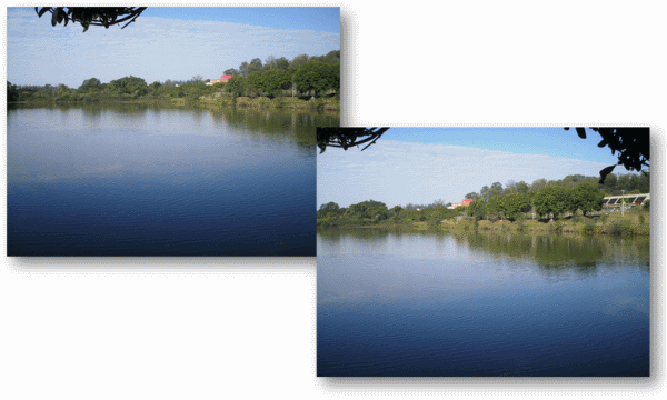
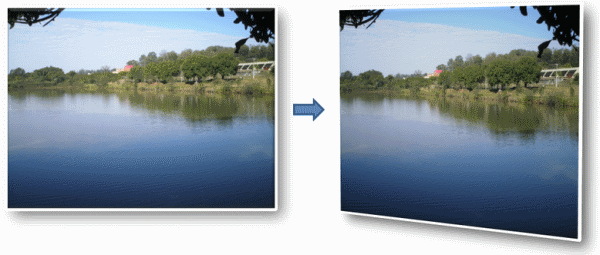
For this demonstration, we will be using these two pictures taken from the UFSCar lake. The pictures have been taken a few degrees apart from each other. We can see that the gymnasium appears only in the second picture, whereas the leftmost portion of the lake appears only in the first picture.
Feature Extraction

In order to create our panorama, the general idea will consist in identifying common points between the two images and then projecting one of the images on top of the other in an effort to match those points. In order to identify those points, which from now on we will be calling interest points, we will be using a simple interest point detector known as the Harris Corners Detector.
While the full description of the Harris detector is beyond the scope of this article (but is available here), I thought it was interesting to include a little history about corner detectors and the Harris operator.
One of the first operators for interest point detection was developed by Hans P. Moravec in 1977 for his research involving the automatic navigation of a robot through a clustered environment. It was also Moravec who defined the concept of "points of interest" in an image and concluded these interest points could be used to find matching regions in different images. The Moravec operator is considered to be a corner detector because it defines interest points as points where there are large intensity variations in all directions. This often is the case at corners. It is interesting to note, however, that Moravec was not specifically interested in finding corners, just distinct regions in an image that could be used to register consecutive image frames.
Harris and Stephens improved upon Moravec's corner detector by considering the differential of the corner score with respect to direction directly. They needed it as a processing step to build interpretations of a robot's environment based on image sequences. Like Moravec, they needed a method to match corresponding points in consecutive image frames, but were interested in tracking both corners and edges between frames.

Pictures of the lake with detected interest points marked in white
While there are better interest point detectors out there, such as SIFT and SURF, those are unfortunately encumbered by patents. In order to allow full commercial usage of this library, I decided to avoid using them and use the Harris detector instead.
Feature Matching
After our interest points have been detected, we need to correlate them somehow. For this, we will be using amaximum correlation rule to determine matches between our two images. The cross-correlation works by analyzing a window of pixels around every point in the first image and correlating them with a window of pixels around every other point in the second image. Points which have maximum bidirectional correlation will be taken as corresponding pairs.

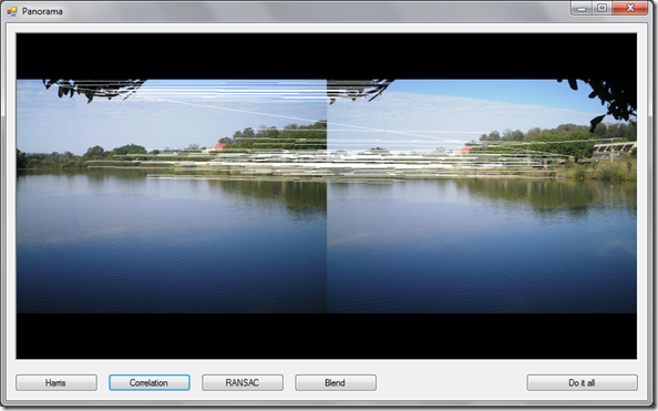
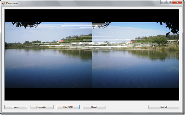
Lake images showing the correspondence relationships among points
We can see from the picture, however, that many points have been wrongly correlated. This is the case of the diagonal lines that do not follow the same direction as the majority of other lines. Nevertheless, we will need not to worry about those for reasons which shall be clear in the next section.
Homography Estimation
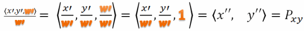
现在我们有了两组相关点,我们要做的就是定义一个模型,它可以将点从一个集合转换到另一个集合。我们正在寻找的是一种图像变换,它可以用来将两个图像中的一个投影到另一个上,同时匹配大部分相关的特征点——我们需要一个与两个图像匹配的同源矩阵。
单应性是投影变换,是射影几何中使用的一种变换。 它描述了当观察者的观点发生变化时观察到的物体的感知位置会发生什么。 在更正式的术语中,单应性是从真实投影平面到将直线映射到直线的投影平面的可逆变换。
通过使用齐次坐标,可以将单应矩阵表示为具有8个自由度的3×3矩阵。
在System.Drawing命名空间中,有一个Matrix类,它封装了一个3乘3的仿射矩阵,表示几何变换。 在Accord.Imaging中,MatrixH类封装了一个表示投影变换的3x3同质矩阵。 两个矩阵之间的差异仅取决于每个矩阵的自由度。

尽管是3x3矩阵,但System.Drawing的几何变换矩阵只有6个自由度,而Accord.NET的投影变换有8个自由度。 在后者中,最后一个值可以解释为比例参数,可以固定为1,如上图所示。 使用齐次坐标是因为单独的矩阵乘法不能直接执行透视投影所需的划分。
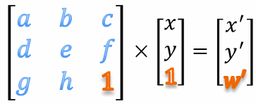
使用齐次坐标,而不是将图像中的每个像素的位置表示为一对<x,y>,我们将其表示为元组<x,y,w>,其中w也是比例参数。 为简化起见,我们将w固定为1。
均匀坐标非常有用,因为它们允许我们通过仅使用标准矩阵乘法来执行图像投影变换,如下面的等式和示意图所示。
一旦计算了所有投影点,我们就可以通过将每个点除以其齐次尺度参数然后丢弃比例因子来恢复我们的原始坐标系,然后将比例因子设置为1。
By estimating the correct values for the homography matrix, we could obtain a transformation like the following:
Which could possibly result in a final projection like this:
Now that we have defined what a homography is and what it is useful for, we can begin to discuss how we can create this homography matrix from our set of correlated points. To estimate a robust model from the data, we will be using a method known as RANSAC.

The name RANSAC is actually an abbreviation for "RANdom SAmple Consensus". It is an iterative method for robust parameter estimation to fit mathematical models from sets of observed data points which may contain outliers. The algorithm is non-deterministic in the sense that it produces a reasonable result only with a certain probability, with this probability increasing as more iterations are performed. The RANSAC algorithm has found many applications in computer vision, including the simultaneous solving of the correspondence problem and the estimation of the fundamental matrix related to a pair of stereo cameras.
The basic assumption of the method is that the data consists of "inliers", i.e., data whose distribution can be explained by some mathematical model, and "outliers" which are data that do not fit the model. Outliers could be considered points which come from noise, erroneous measurements, or simply incorrect data.
For the problem of homography estimation, RANSAC works by trying to fit several models using some of the point pairs and then checking if the models were able to relate most of the points. The best model, i.e., the homography which produces the highest number of correct matches, is then chosen as the answer for the problem.

After the execution of RANSAC, we can see only the correct matches were left in our images. This happens because RANSAC did find a homography matrix relating most of the points, and discarded the incorrect matches as outliers.
The full explanation of RANSAC is way beyond the scope of this article, but more information about a RANSAC implementation in C# can be found here.
Blending
After our homography matrix has been computed, all that is left for us is to blend the two images together. To do so, we will be using a linear gradient alpha blending from the center of one image to the other. The gradient blending works by simulating a gradual change in one image's alpha channel over the line which connects the centers of the two images.
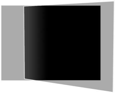
The image shows the linear gradient used by the blending filter. The leftmost gray part of the image represents the left picture of the lake. The rightmost part represents the right picture of the like. The inner part shows the linear gradient which blends one image to the other. The first, grayest color of the gradient represents the first image, while the darkest color represents the second image. The transition indicates how much of each image will be present in the final blending.
Results
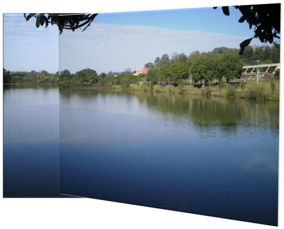
After the blending filter has been applied, we will finally have our result as shown in the image below:

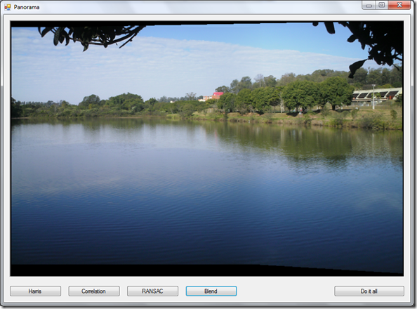
Final image resulting from the blending of the two consecutive lake images
Source Code
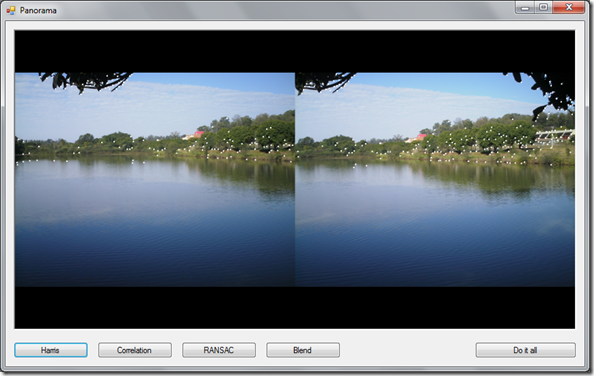
Using Accord.NET, the code for image stitching becomes extremely simple. Remember, we will need to perform four steps: Interest point detection, Correlation matching, Robust homography estimation, and Gradient blending. So before going into those steps, let's define a few class variables (this code was taken from the sample application code):
Collapse | Copy Code

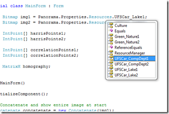
// Images we are going to stitch together private Bitmap img1 = Panorama.Properties.Resources.UFSCar_Lake1; private Bitmap img2 = Panorama.Properties.Resources.UFSCar_Lake2; // Fields to store our interest points in the two images private IntPoint[] harrisPoints1; private IntPoint[] harrisPoints2; // Fields to store our correlated points private IntPoint[] correlationPoints1; private IntPoint[] correlationPoints2; // The homography matrix estimated by RANSAC private MatrixH homography;
The source code accompanying this article contains the sample application plus only a small subset of the Accord.NET Framework to avoid cluttering namespaces. If you wish to use Accord.NET, please be sure to download the latest version from the project page at Origo. By the way, the sample application assumes you will just push buttons in the right order. If you call a step before the previous steps have been computed, you will most probably get an exception. This is just to reflect the code that is needed for the stitching. It is also exactly the same code shown in the next sections.
Interest Point Detection
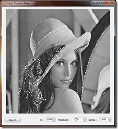
To perform interest point detection, we will be using the Accord.Imaging.HarrisCornersDetector class. To make the process faster, we could use a higher suppression threshold for suppressing some points. For this example, we will be using 1000.
Collapse | Copy Code
private void btnHarris_Click(object sender, EventArgs e) { // Step 1: Detect feature points using Harris Corners Detector HarrisCornersDetector harris = new HarrisCornersDetector(0.04f, 1000f); harrisPoints1 = harris.ProcessImage(img1).ToArray(); harrisPoints2 = harris.ProcessImage(img2).ToArray(); // Show the marked points in the original images Bitmap img1mark = new PointsMarker(harrisPoints1).Apply(img1); Bitmap img2mark = new PointsMarker(harrisPoints2).Apply(img2); // Concatenate the two images together in a single image (just to show on screen) Concatenate concatenate = new Concatenate(img1mark); pictureBox.Image = concatenate.Apply(img2mark); }
Correlation Matching
Using Accord.NET, correlation can be achieved by using the Accord.Imaging.CorrelationMatching class. In this example, we will be considering a window of 9 pixels around each point.
Collapse | Copy Code
private void btnCorrelation_Click(object sender, EventArgs e) { // Step 2: Match feature points using a correlation measure CorrelationMatching matcher = new CorrelationMatching(9); IntPoint[][] matches = matcher.Match(img1, img2, harrisPoints1, harrisPoints2); // Get the two sets of points correlationPoints1 = matches[0]; correlationPoints2 = matches[1]; // Concatenate the two images in a single image (just to show on screen) Concatenate concat = new Concatenate(img1); Bitmap img3 = concat.Apply(img2); // Show the marked correlations in the concatenated image PairsMarker pairs = new PairsMarker( correlationPoints1, // Add image1's width to the X points // to show the markings correctly correlationPoints2.Apply(p => new IntPoint(p.X + img1.Width, p.Y))); pictureBox.Image = pairs.Apply(img3); }
Robust Homography Estimation
Here, we will be using the Accord.Imaging.RansacHomographyEstimator class for estimating homography matrices using RANSAC. RansacHomographyEstimator is a convenience class encapsulating all the logic used to setup an Accord.MachineLearning.RANSAC object with the parameters for fitting a homography matrix.
Collapse | Copy Code
private void btnRansac_Click(object sender, EventArgs e) { // Step 3: Create the homography matrix using a robust estimator RansacHomographyEstimator ransac = new RansacHomographyEstimator(0.001, 0.99); homography = ransac.Estimate(correlationPoints1, correlationPoints2); // Plot RANSAC results against correlation results IntPoint[] inliers1 = correlationPoints1.Submatrix(ransac.Inliers); IntPoint[] inliers2 = correlationPoints2.Submatrix(ransac.Inliers); // Concatenate the two images in a single image (just to show on screen) Concatenate concat = new Concatenate(img1); Bitmap img3 = concat.Apply(img2); // Show the marked correlations in the concatenated image PairsMarker pairs = new PairsMarker( inliers1, // Add image1's width to the X points to show the markings correctly inliers2.Apply(p => new IntPoint(p.X + img1.Width, p.Y))); pictureBox.Image = pairs.Apply(img3); }
Gradient Blending
The final step is to create a blending of the two images. For this, we will be using the Accord.Imaging.Blendfilter, which is implemented as an AForge.NET image filter.
Collapse | Copy Code
private void btnBlend_Click(object sender, EventArgs e) { // Step 4: Project and blend the second image using the homography Blend blend = new Blend(homography, img1); pictureBox.Image = blend.Apply(img2); }
Doing It All At Once
To perform everything in a single step, we can use the following code in a single button:
Collapse | Copy Code
private void btnDoItAll_Click(object sender, EventArgs e) { // Do it all btnHarris_Click(sender, e); btnCorrelation_Click(sender, e); btnRansac_Click(sender, e); btnBlend_Click(sender, e); }
And this finishes the entire code needed for automatic image stitching!
Sample Application
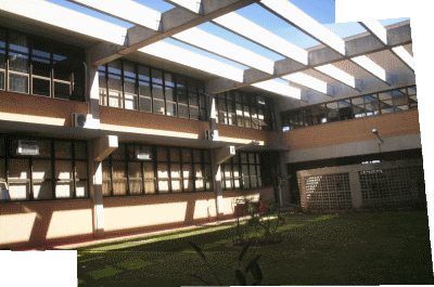
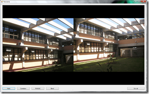
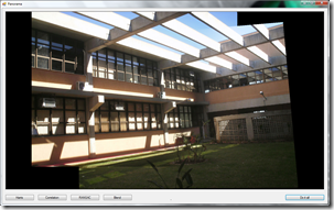
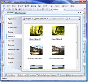
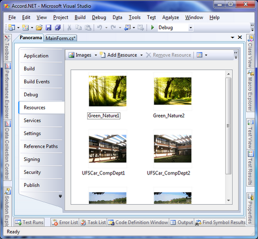
The sample application comes with other two sets of photos, one taken from inside of the UFSCar Computing Department building, and another taken from a random wallpaper found in the web. Below are the screenshots from the application stitching two pictures of the computing department.
|
|
|


Images from inside the Computing Department
However, in order to use the additional images, it will be necessary to add them to the project resource file and then select them in the code. Or, you could add your own image loading dialogs. I avoided using file open dialogs in order to show only a compact and direct view of the stitching methods.
|
|
|

Remarks
RANSAC is a probabilistic algorithm. This means it may generate different outputs on every execution, and may produce a correct answer only within some probability. So the quality of the final result may vary wildly if RANSAC parameters are not chosen wisely. Also, as you may have noted, there are many parameters to tweak in each step of the stitching method. Choosing the correct values for the parameters may have a direct influence on the quality and the time spent for producing the result.
Known Issues
The implementation, as it is, does not perform very well on images with very different lighting conditions. To avoid this situation, we should normalize the two images before starting the method.
Another known issue is the quality of the Blending filter. While it may perform well on images displaced laterally, it may perform poor on images displaced on the diagonal. As it can be seen in the stitching using the Computing Department pictures, a distinct horizontal line will be visible between one image and the other.
Further Works
This code is well suited for the automatic panorama creation for a pair of images. However, as it stands, it still can not be used to create full panoramas using an arbitrary number of images. In order to extend the code for the case of multiple images, we could form panoramas by recursively taking pair of images from the total set of images and then blending them forming a single image.
The code could also be extended to create image mosaics in which we don't know the correct order of the images beforehand, by considering a minimum threshold of correlation between two images before attempting a match. This way, only images with strong correspondences are stitched at a time, and a full mosaic could again be constructed recursively.
Conclusion
In this article, we have seen how automatic panorama creation is possible using well-defined and simple processing steps. Those steps are already available in Accord.NET, an Open-Source (LGPL) framework built on top of AForge.NET(also LGPL). For a complete set of the features currently available in Accord.NET, please see http://accord-net.origo.ethz.ch/wiki/features.
Acknowledgements
To Andrew Kirillov, author of the excellent AForge.NET Framework, for the effort and time spent building his framework. The C# community was really in need of such a great project.
References
- P. D. Kovesi. MATLAB and Octave Functions for Computer Vision and Image Processing. School of Computer Science & Software Engineering, The University of Western Australia.
- D. Parks and J. P. Gravel. Corner Detectors: The Harris/Plessey Operator. Web. 11 May, 2010.
- J. Hutton and B. Dowling. Computer Vision Demonstration Website. Electronics and Computer Science, University of Southampton.
- H. P. Moravec. Towards Automatic Visual Obstacle Avoidance. Proc. 5th International Joint Conference on Artificial Intelligence, pp. 584, 1977.
- H. P. Moravec. Visual Mapping by a Robot Rover. International Joint Conference on Artificial Intelligence, pp. 598-600, 1979.
- C. Harris and M. Stephens. A Combined Corner and Edge Detector. Proc. Alvey Vision Conf., Univ. Manchester, pp. 147-151, 1988.
- A. Kirillov. The AForge.NET Framework. The AForge.NET Computer Vision, Artificial Intelligence and Robotics Website, 2010.
- Wikipedia contributors. "RANSAC" Wikipedia, The Free Encyclopedia.
- Wikipedia contributors. "Corner detection" Wikipedia, The Free Encyclopedia. 5 May, 2010. Web. 11 May, 2010.
License
This article, along with any associated source code and files, is licensed under The Code Project Open License (CPOL)
About the Author
转载自原文链接, 如需删除请联系管理员。
原文链接:image stitch(国外开源的图像拼接),转载请注明来源!